Week 10: Machine Design

Concept of the Instrument Machine
Our initial idea was to build an instrument from a guitar string that plays autonomously and replicates the frequency of the played guitar string through a visualizer.
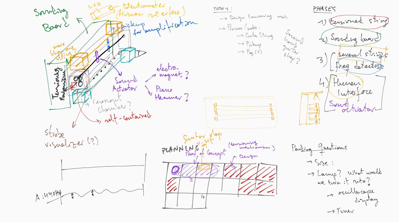
Group Brainstorming
In a brainstorming session, we outlined the various tasks:
- Motor and gearbox
- Electronics (frequency detection and electronic board design)
- Housing construction (frame to hold the machine and resonant chamber)
- Display (to show the detected frequency)
Based on our availability over Easter, we began working on it.
Motor and Gearbox
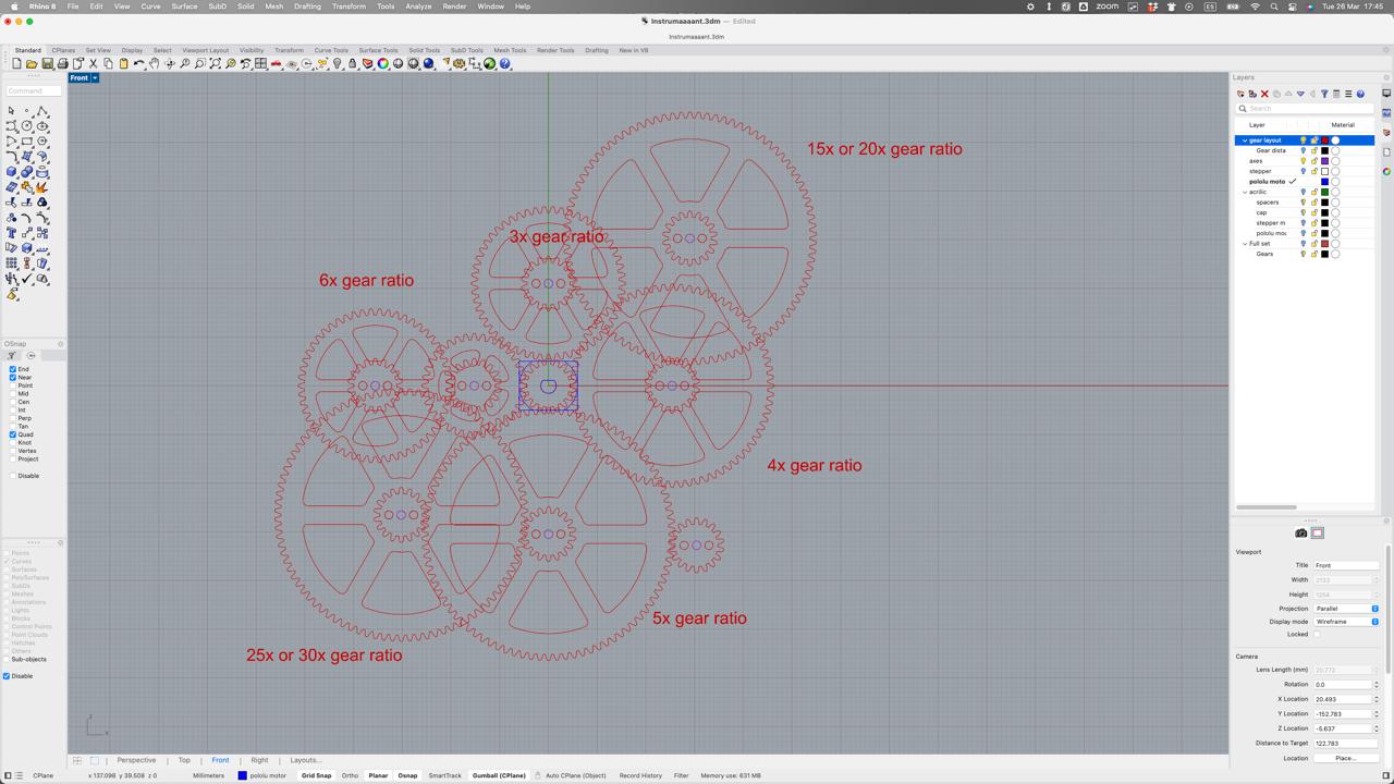
We created a prototype of the gearbox. This test gearbox can house either a 9V DC Pololu motor or a 35mm stepper motor. It has openings to mount gears in different combinations, allowing us to test various reduction ratios. The gearbox is laser cut from acrylic, with 1.6mm thick brass axles.
We used this website to create the gears: Gear Generator
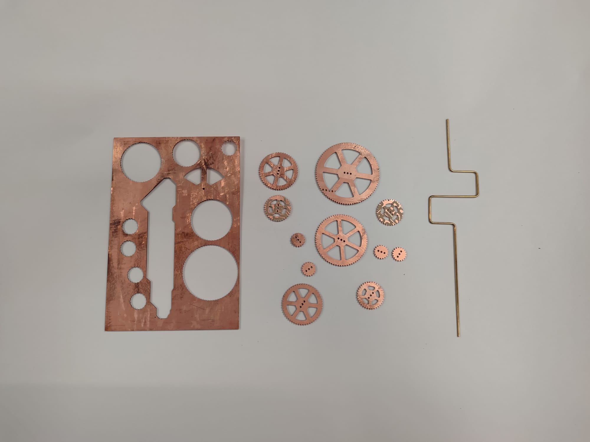
Initially, we tested the gearbox with gears cut from waste PCB material, but the gears were too small. They were difficult to mesh and tended to flex out of alignment. We then switched to acrylic, which required larger teeth, but it worked very well.
Cutting
After testing, we decided to cut and create the gears and the box in acrylic. We had to adjust the file for the cut and created various versions. Initially, we faced difficulties because the cutter did not cut through the acrylic sheet. However, after switching to a different laser cutter, it worked. We also had to extend the teeth of the gears to ensure they meshed better.
The design positions the motor below the gearbox. The motor drives the gears, which ultimately move a component of the guitar to which the guitar string is attached. It was crucial that all elements were precisely attached to avoid excessive movement. Despite careful measurements, it took us some time to cut and assemble everything accurately.
Electronics
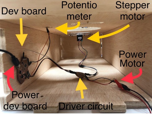
Maxence and Dani worked on the electronics. The board needs to accommodate:
- A processor powerful enough to analyze sound and extract its dominant frequency in real-time.
- Programming connections (e.g., JTAG).
- A power source capable of controlling a 9V motor.
- Connections for a stepper motor.
- A power source that can drive a strip of LEDs and switch them on and off at frequencies between 100-1000Hz (optional, but useful if we reach that point).
- Connections for an LCD screen.
- Connections for at least one potentiometer and one button.
- LED status indicators.
Design Process
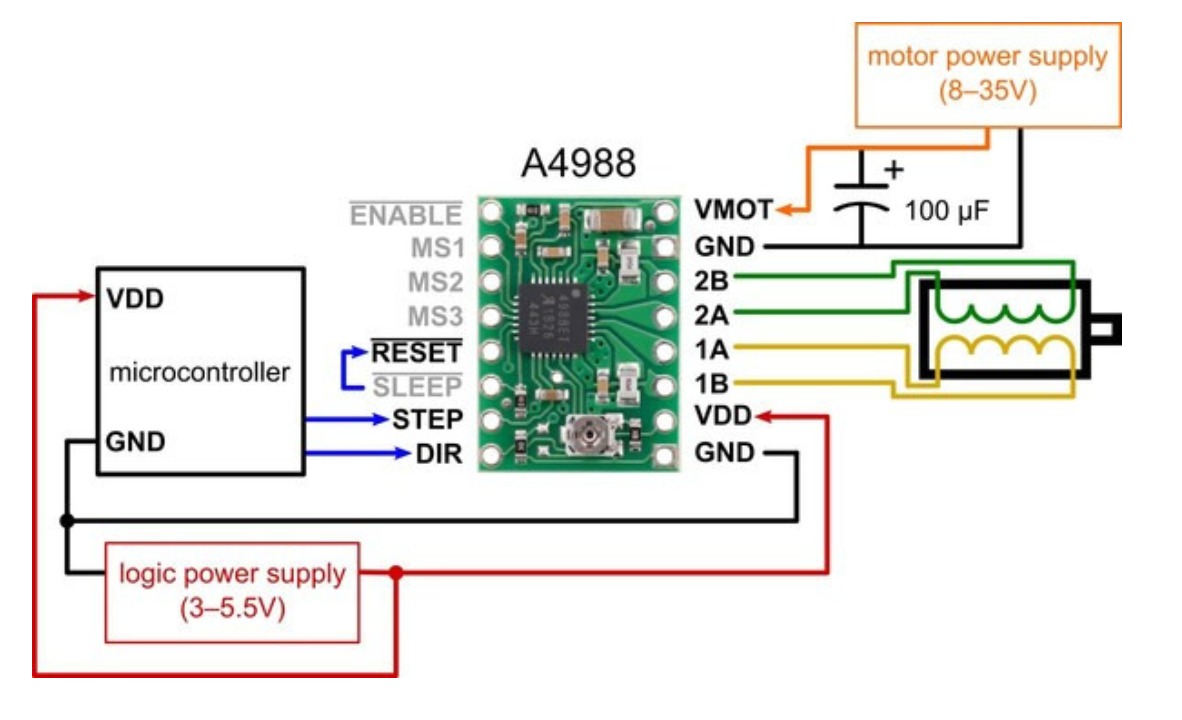
They need to integrate a stepper motor driver into the board. The quickest way to achieve this was by using an A4988 breakout board, which we have available. It was necessary to provide it with an adequate voltage supply: 12V or more.
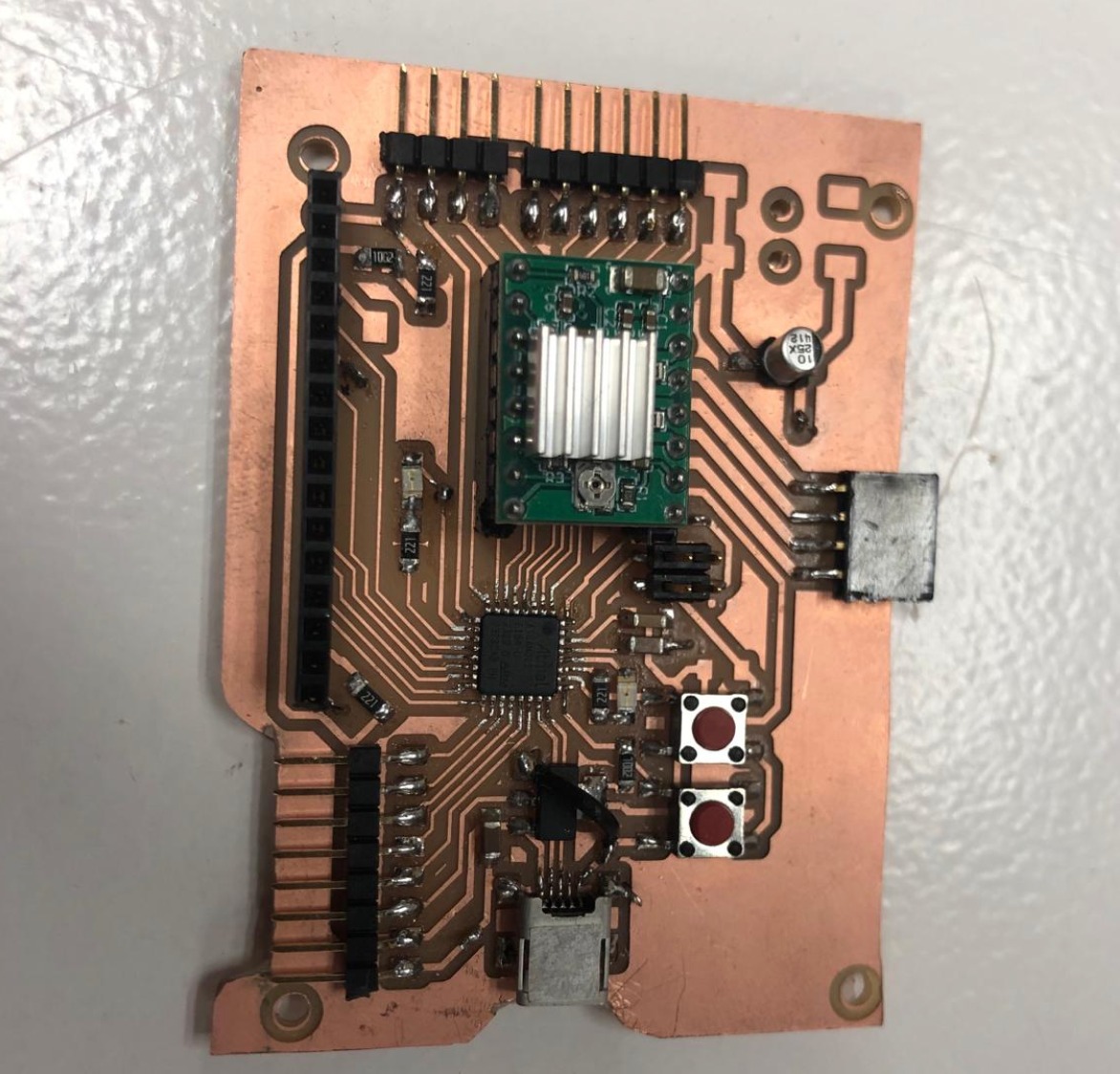
Cutting
The board needs to be double-sided to allow for soldering the stepper motor mount. The process is as follows:
- Front copper with 1/64 endmill
- Alignment holes with 1/32
- Insert pins into the sacrificial board
- Cut off pin heads
- Lift the board, remove the double-sided tape, apply tape to the other side, and realign using the pins as guides
- Back copper with 1/64
- Holes with 1/32
- Outline with 1/32
Between each step, the Z-axis needs to be rezeroed while keeping the XY reference constant. The first version of the board didn't work as expected, so we abandoned the custom board requirement and used a development board we had previously made.
Gears
As described, we worked on various topics within the group. Naturally, we delved into and supported all topics as much as we could. Personally, I focused mainly on two topics: Gearbox and Housing Construction.
Gears are mechanical components with teeth that mesh together to transmit rotational motion and force between different parts of a machine or device. They are used to change or adjust the rotational speed, direction of rotation, and torque.
One member of our group quickly developed a prototype of the gearbox. It worked well but was not aesthetically pleasing and did not operate smoothly. Additionally, we wanted to use a different material. However, we already had the drawings, so we didn't have to start from scratch. Nonetheless, there was still a lot to do. We decided to cut with Laysercut Acrylic. Initially, we opted for a thin acrylic plate. However, during the process, we switched to a thicker acrylic plate.
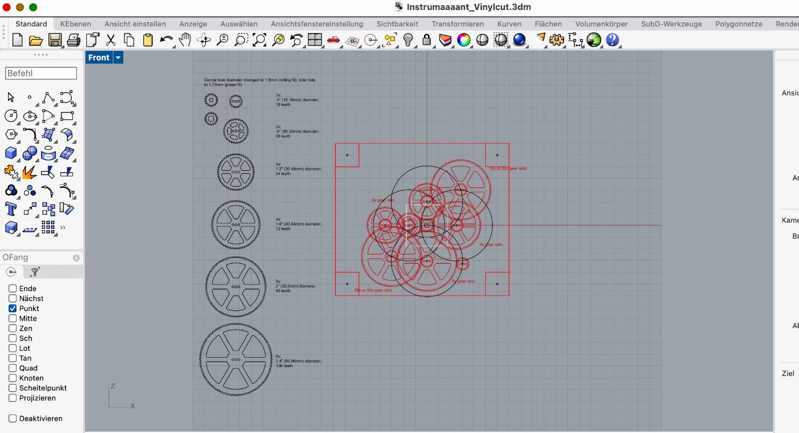
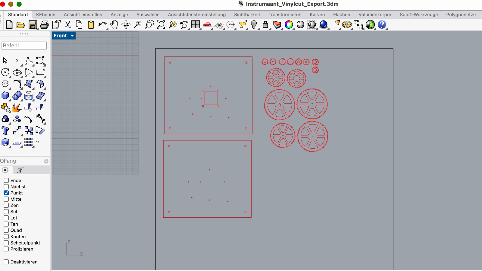
The pictures show the file we used and how we adjusted it. In the first step, we left the sizes of the gears as they were. However, we adjusted the centers of the gears because we wanted to connect them via different elements that had different sizes. I recreated the file.
With the finished file, we went to the laser cut machine. We performed the first cut. Unfortunately, the gears were much too small, so we couldn't use them. We found that we hadn't set the size properly in the program on the machine. It wasn't set to 100% print size.
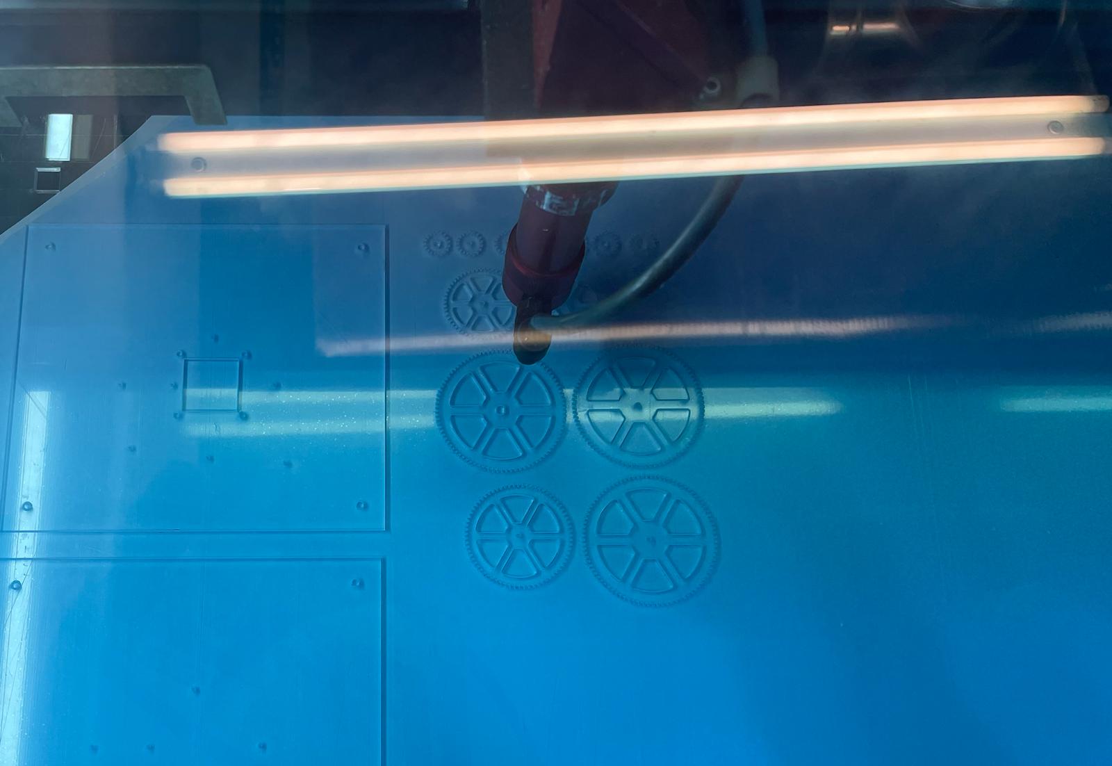
It took us a while to find the right parameters to cut the vinyl. We only cut out a test square each time. But it wasn't cut properly. In the end, we decided to use a different machine. There, the laser cut worked better.
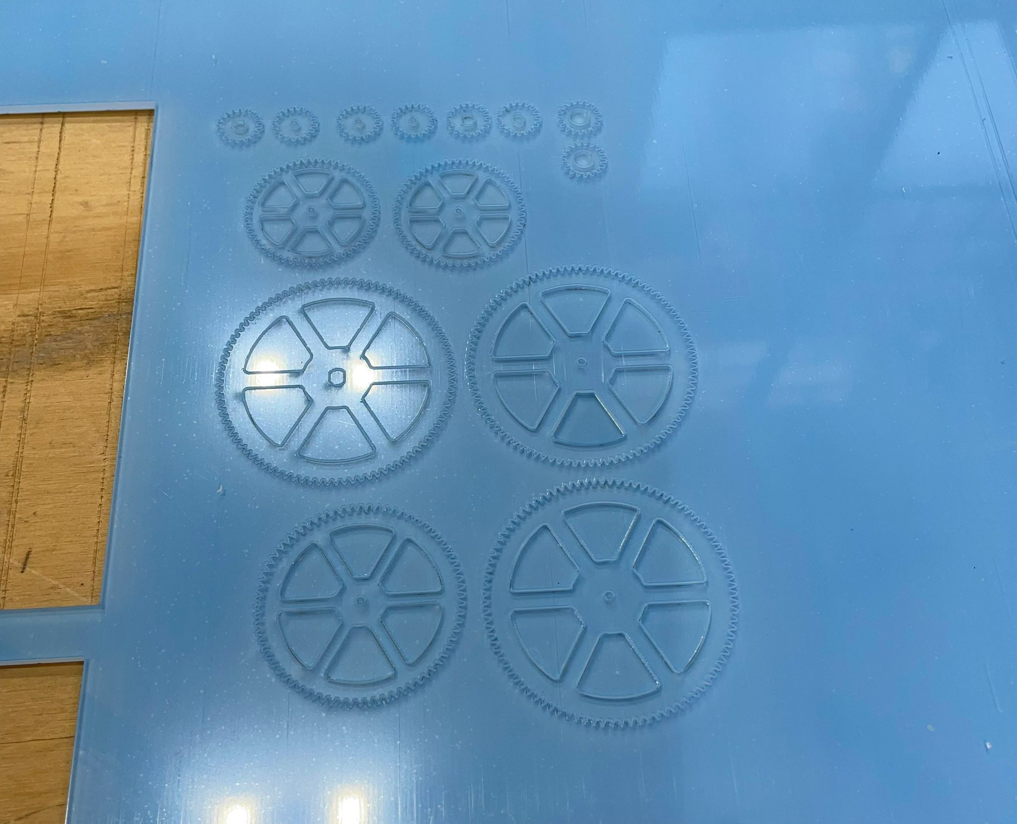
We then removed the gears from the Acryl and assembled the gears for the first time. It worked, but the gears were very delicate, so they didn't grip perfectly. The plan was therefore to change the size of the gears again.
Housing Box
Since we hadn't found anyone to build the wooden box, I took over this process and handed over the gearbox to another group member.
For the resonance box, we decided to build a wooden box. The wooden box should fulfill the following tasks:
- Form a resonant chamber that amplifies sound
- Hold the motor and the gearbox
- Serve as an attachment for the string
- Hold the bridge to allow the guitar string to pass over it
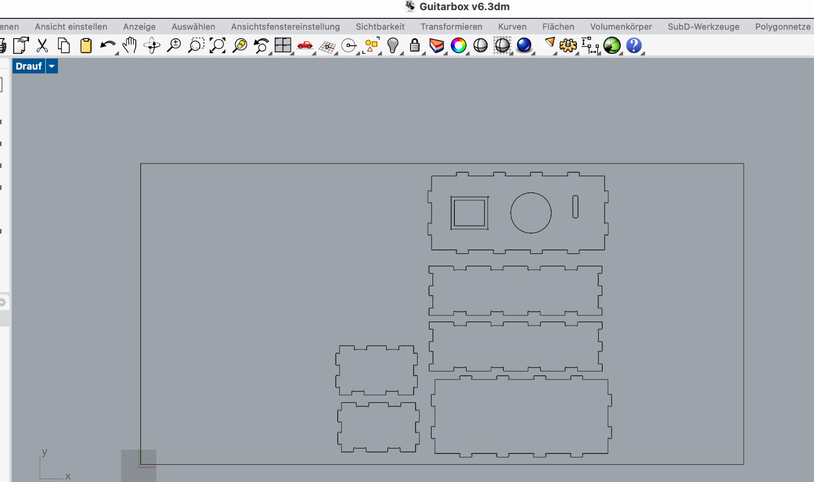
I started designing the box in Fusion. To cut it with the CNC machine, I need to edit it later in Rhino CAM.
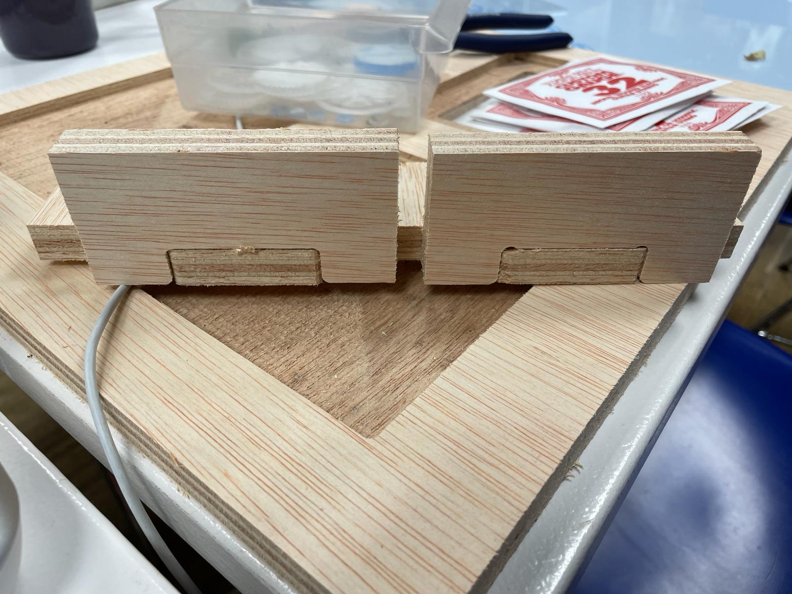
I worked on an initial sketch with Fusion. I used sketch mode and the parameter option to easily change individual parameters later if necessary.I prepared the hole sketch and also some pieces to do a joinery test.
The following steps must be carried out to prepare for the CNC cut:
- Save the Fusion file as a DXF file
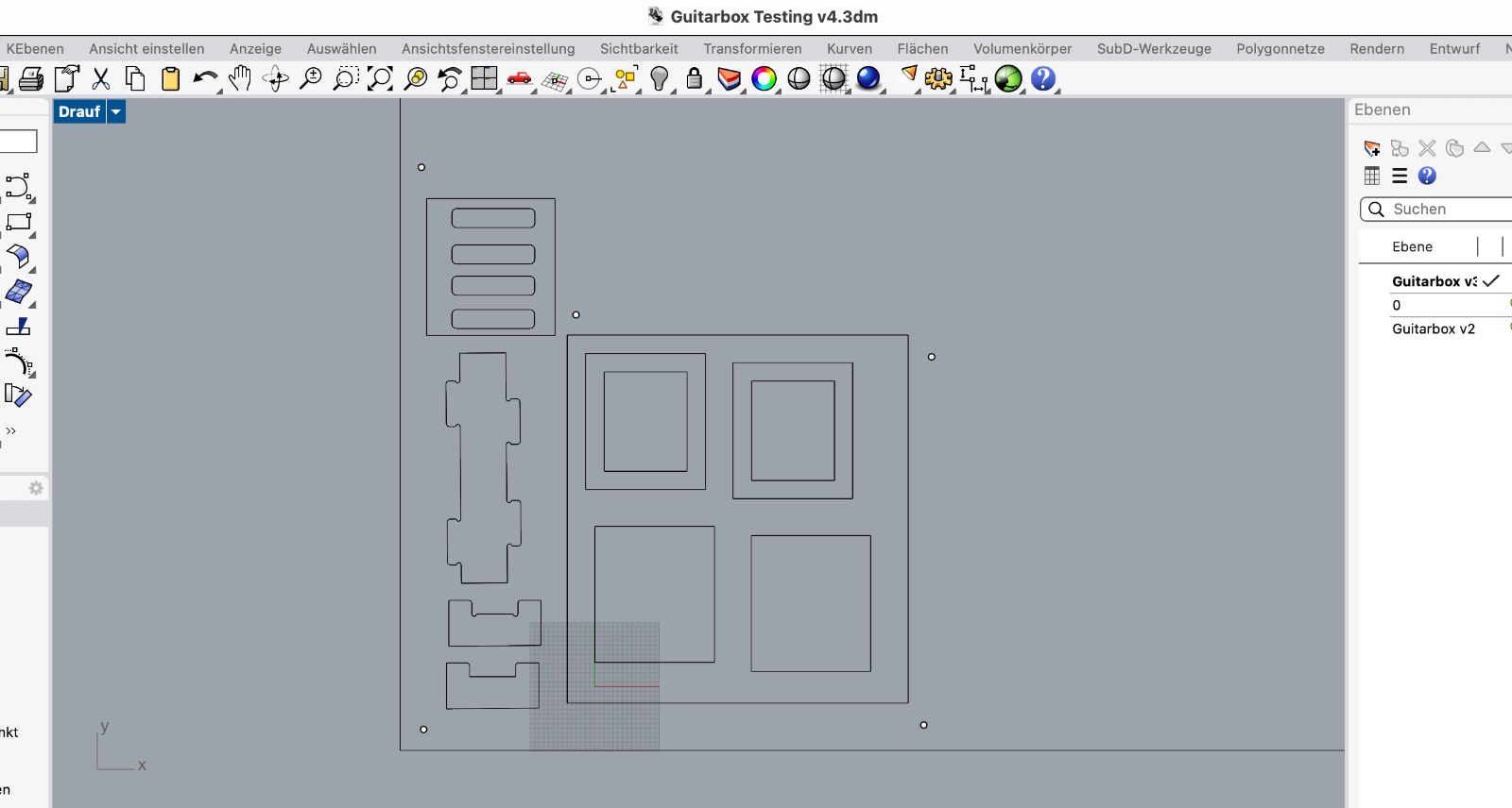
- Open the DXF file in Rhino
- Prepare the cutting plan - important: connect all individual parts using the "join" command
- Save the Rhino file as a Rhino 5 file
- Open the Rhino file on a computer with Rhino CAM and prepare it for cutting
- First, set points for the screws
- Then adjust all parameters for pocketing and cutting
- First, save the screw file as a post
- Then save all other files as posts
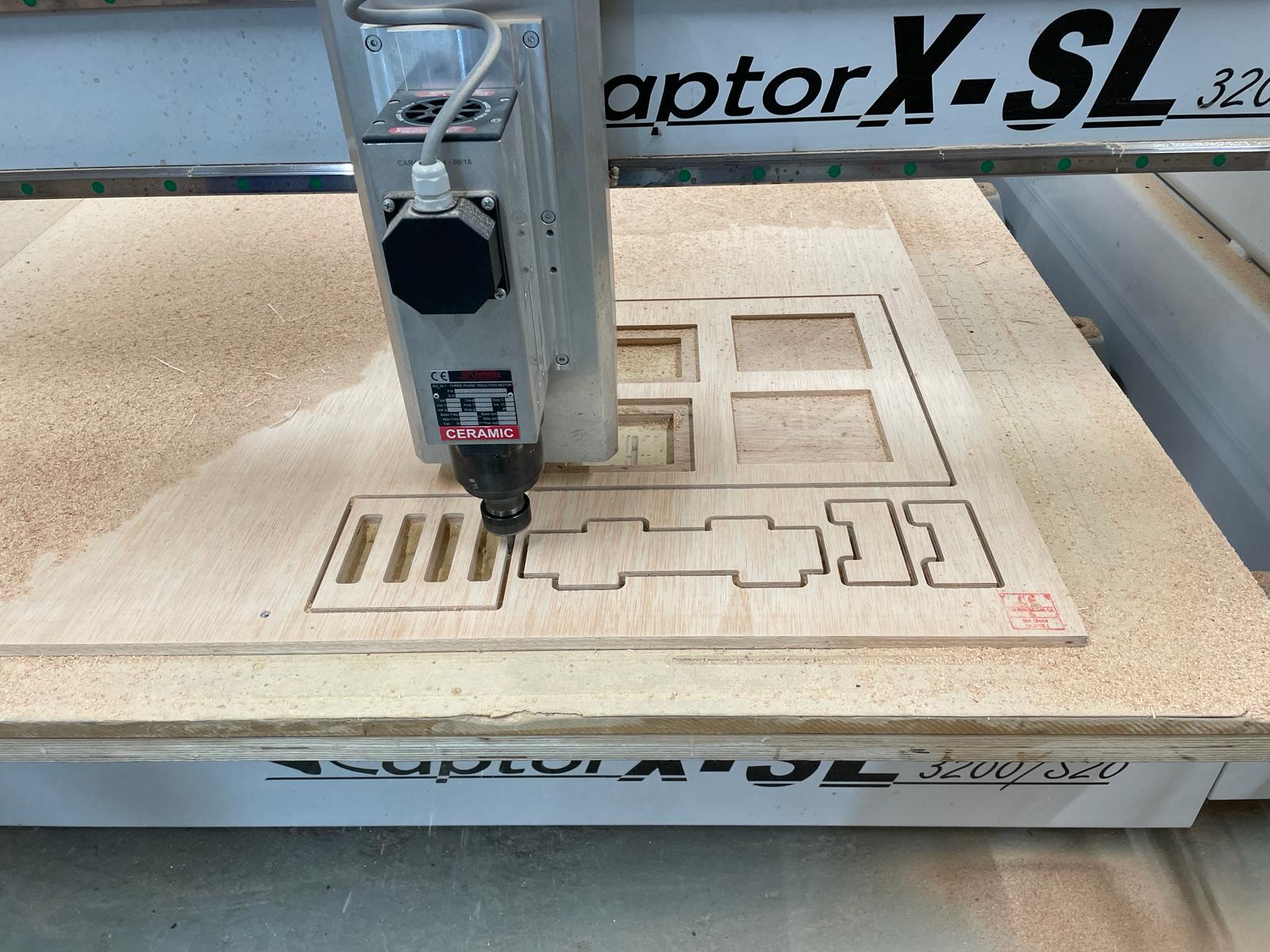
I initially tested the joineries. Some of the parts fit very well, while others needed adjustments.
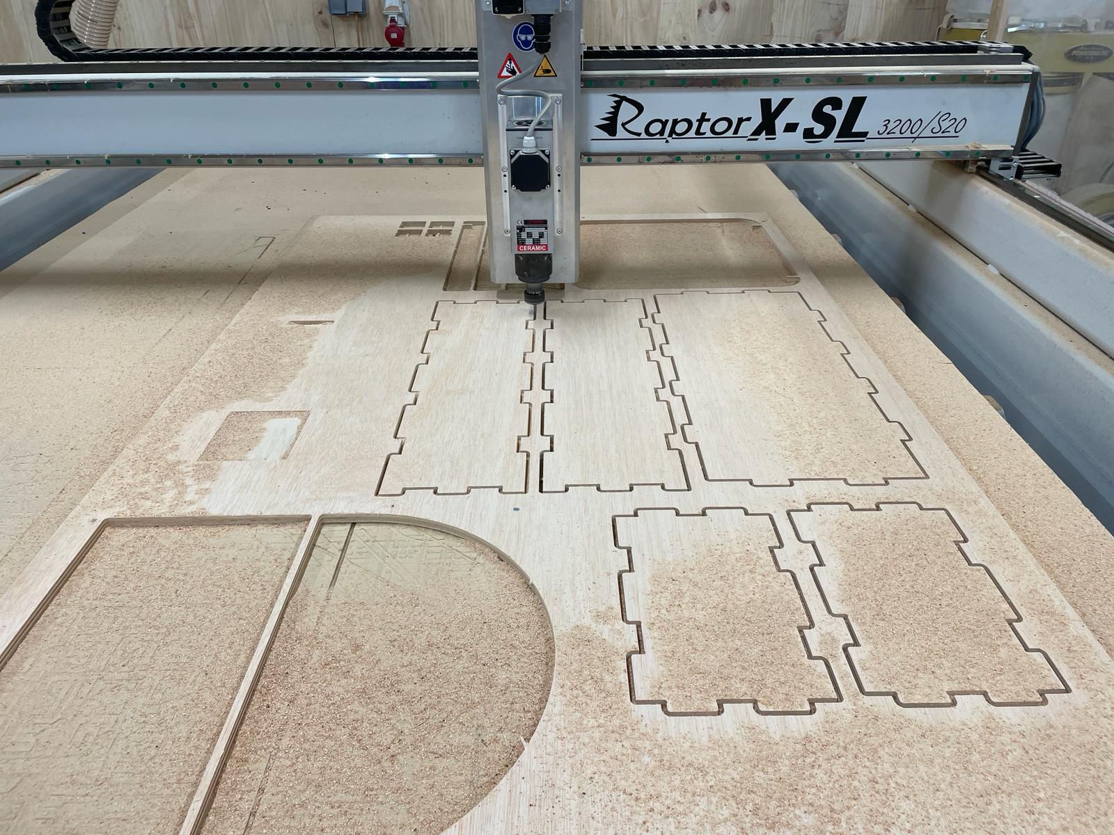
After that, I adjusted the cutting plan and cut out the complete box.
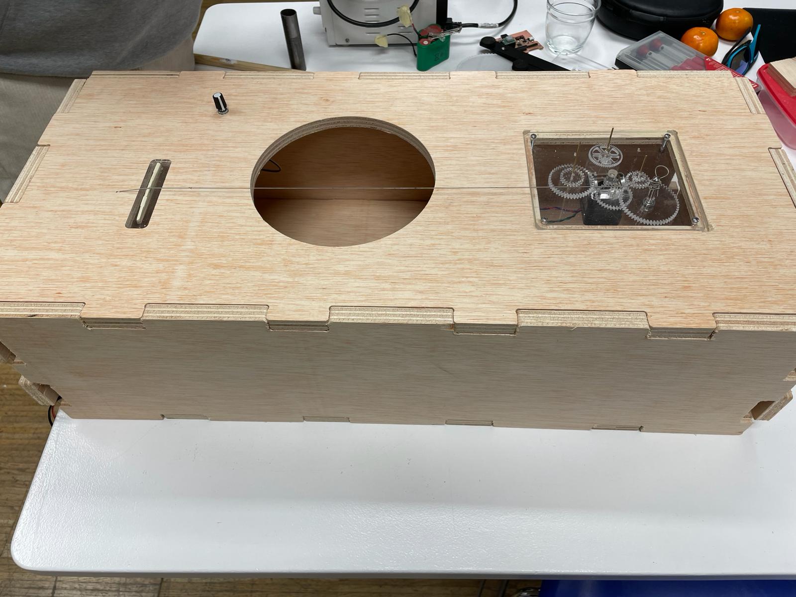
Prototype
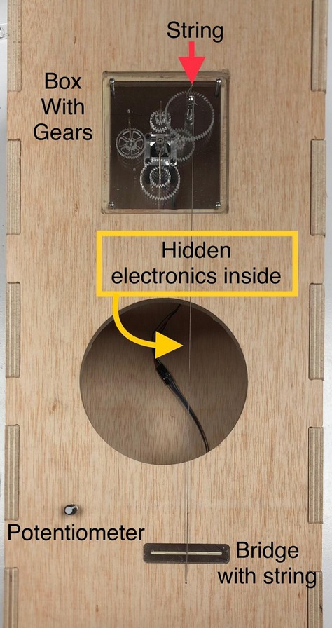
The gears are housed in a visible box made of PMMA, to which the string is attached. The string is stretched over a bridge on the front panel of the instrument.
Next to the circular opening in the front panel, there is a potentiometer that allows you to adjust the tension of the string. Turning it clockwise increases the tension, while turning it counterclockwise decreases the tension. Adjusting the tension changes the frequency of the string, allowing you to play both high and low notes on the same string.
The electronics are hidden inside the box.